L3 MPLS VPN on Brocade Ironware
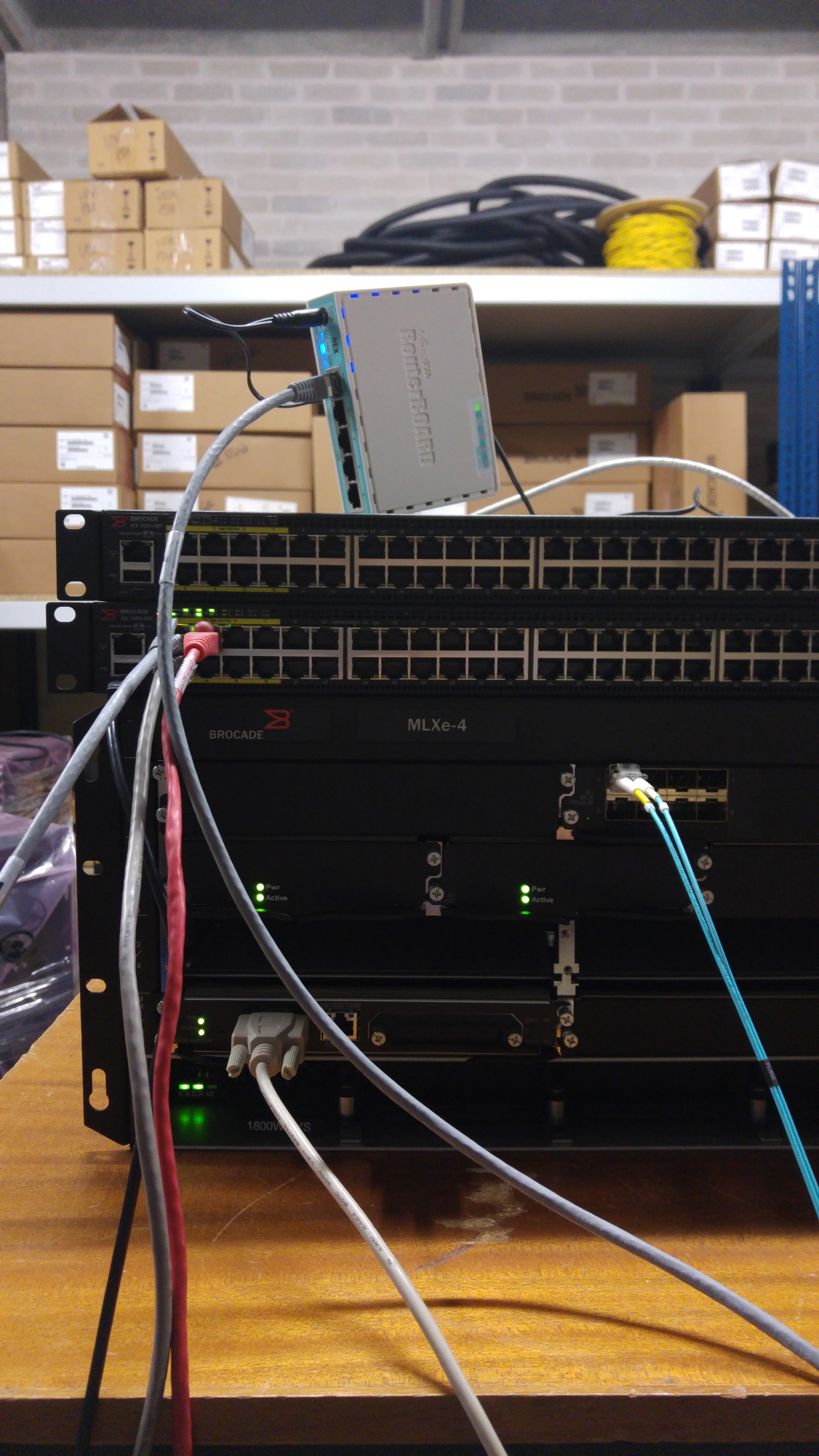
This might seem a bit of an odd post to be making. Not just because the MLXe router we’re using will probably be painted a very fetching shade of purple in future editions, but also due to a lack of spare hardware, I had to pair it up with a Mikrotik hEX.
’twas a bit of a little and large situation.
In all seriousness, our aim is to get the two core routers to build an L3 VPN tunnel over MPLS. We’ll be using BGP to advertise the ends of the tunnel, allowing us to very easily expand out.
In short, our two routers will be provider edge routers, the MLXe towards the bottom of the diagram and the hEX futher up.
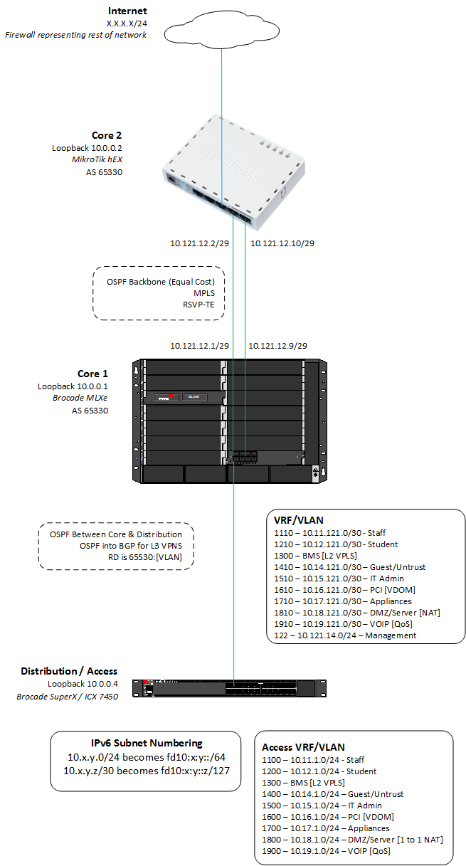
Throughout this we will be concentrating on the MLXe side of things. The documentation on the Mikrotik wiki has enough great examples to get through the process.
The starting point is two routers with loopback interfaces sharing routes via. OSPF. Everything is built on top fo the basic L3 network. The required configuration to make this happen looks a little like this:
router ospf
    area 0
interface loopback 1
    ip ospf area 0
    ip ospf passive
    ip address 10.0.0.1/32
vlan 121
    untagged ethe 2/1
    router-interface ve 121
interface ve 121
    ip ospf area 0
    ip address 10.0.121.1/29
Assuming all is well, you should be able to ping between the two loopback interfaces. If not, debug the problem before going any further, we need a working base to start with.
We can now enable MPLS and use LDP to distribute labels across the network. Note that you’ll need a line card with support for MPLS installed for this to work.
router mpls
    mpls-interface ve 121
    ldp-enable
At that point not much will appear to have changed, even though a lot has. You should still be able to ping. However, if you run the show mpls ldp database command, you’ll see that the next hop maps onto a label. That’s the label that will be attached as the packed is encapsulated between the routers.
In order to keep the VPN we’re building separate from the underlying network and any other VPNs we may implement later, we’ll be placing it into a virtual routing and forwarding (VRF) instance.
vrf blue
    rd 65530:2
    route-target export 65530:2
    route-target import 65530:2
    address-family ipv4
    exit-address-family
    address-family ipv6
    exit-address-family
exit-vrf
vlan 210
    tagged ethe 2/1
    router-interface ve 210
interface ve 210
    vrf forwarding Blue
    ip address 10.2.10.0/24
There’s a lot going on here so let’s break it down. To start with the name for the VRF instance is completely arbitrary. Pick an appropriate name for your own implementation.
One of the more interesting bits is rd 65330:2. That’s the route distinguisher we’re attaching to the VRF. It’s merely a unique ID we’ll be using throughout the infrastructure. In a larger network each customer would one to separate their routes.
The format for the route descriptor is usually [AS Number]:[Number]. Throughout this example, we’ll be using the AS number 65530. You can use your real AS number if you have one. Otherwise, pick a private number.
Either way, in our smaller campus network, the route descriptor is used to divide network roles. The AS number will be consistent but the route descriptor will be specific to the VPN.
The route target inbound and outbound settings is where we actually make use of this. The route descriptor we use for a specific circuit or customer could be different at both ends. Here, we can set what route descriptor will be used for when we export or import routes. In our case BGP is the routing protocol of choice.
Beyond this, we simply enable IPv4 and IPv6 for the VRF in question. The latter configuration is an example of how to get a VLAN and virtual routing interface into a specific VRF.
With the local routing instance now ready to go, we can look at configuring BGP to pass the routes required for the VPN to work.
router bgp
    local-as 65530
    next-hop-mpls
    neighbor 10.0.0.2 remote-as 65530
    neighbor 10.0.0.2 update-source 10.0.0.1
    address-family vpnv4 unicast
        neighbor 10.0.0.2 activate
        neighbor 10.0.0.2 send-community extended
    exit-address-family
    address-family vpnv6 unicast
        neighbor 10.0.0.2 activate
        neighbor 10.0.0.2 send-community extended
    exit-address-family
    address-family l2vpn vpls
        neighbor 10.0.0.2 activate
        neighbor 10.0.0.2 send-community extended
    exit-address-family
    address-family ipv4 unicast vrf Blue
        neighbor 10.0.0.2 remote-as 65530
        redistribute connected
    exit-address-family
That’s a lot of configuration to hit you with in one go. Let’s break it down bit by bit.
router bgp
    local-as 65530
    next-hop-mpls
    neighbor 10.0.0.2 remote-as 65530
    neighbor 10.0.0.2 update-source 10.0.0.1
Here we set the router’s Autonomous System (AS) number. The AS model is a core part of the BGP infrastructure. In our model, we’ll be using the same AS number on all of the routers.
The next-hop-mpls line tells the router to prefer MPLS over IP routing for the next hop. Finally, we set our neighbour (or peer) up on 10.0.0.2 with the same AS number and updating from the loopback interface. If you’re talking to routers from other vendors, you may need to enable multi-hop for connections between peers.
    address-family vpnv4 unicast
        neighbor 10.0.0.2 activate
        neighbor 10.0.0.2 send-community extended
    exit-address-family
    address-family vpnv6 unicast
        neighbor 10.0.0.2 activate
        neighbor 10.0.0.2 send-community extended
    exit-address-family
    address-family l2vpn vpls
        neighbor 10.0.0.2 activate
        neighbor 10.0.0.2 send-community extended
    exit-address-family
    address-family ipv4 unicast vrf Blue
        neighbor 10.0.0.2 remote-as 65530
        redistribute connected
    exit-address-family
And now for where the real magic happens. Here, we enable VPNv4/v6 to advertise our tunnels. The extended communities are enabled for each peer.
The requirement to configure for each peer is a bit of a sticking point in BGP. In a small setup like this (two routers), we can manage the peering. When the number of routers expands out, a full mesh needs to be maintained. The use of route reflectors allows you to move away from this requirement and should be considered in larger designs.
The final stanza is where we actually start to advertise the routes for our VPN. It’s also the slightly confusing element.
We enable IPv4 routing for BGP on the VRF we created earlier. Again, we must specify the neighbours/peers we’ll be tunnelling between.
The redistribute connected line is something you probably won’t see in a production configuration. It redistributes routes for all connected interfaces in that VRF into BGP.
In most cases, you’ll either see the redistribution of OSPF routes into the BGP VPN or even another instance of BGP on a different AS number. If you were on the customer side of this arrangement, you’d have to specifically configure BGP to allow routes to pass for your own AS number through another AS.
Either way, that’s all it takes to configure L3 MPLS VPNs using BGP on Brocade Netiron hardware. Next steps on my own journey are to enable dynamic routing from VRFs at the distribution layer, experiments with RSVP for guaranteeing bandwidth and demoing 802.1x on the wire. None of it’s new stuff to me but it’s an interesting exercise bringing it all together.