MPLS in a Full Mesh Core with Dual Homed CE Routers
We’re making a fairly substantial change to our core network in the New Year. It’s seeing us move from a flat, L3 routed network to an MPLS fabric. This option was chosen over VRF lite in order to allow for L2 VPNs for a later convergence project. Ideally, we’d be stretching that fabric down to the distribution layer (something we definitely will be doing in the future) but current equipment limitations prevent this. The joy of still having Brocade SuperX units in live service.
Anyhow, a simplified version of our network looks a bit like this:
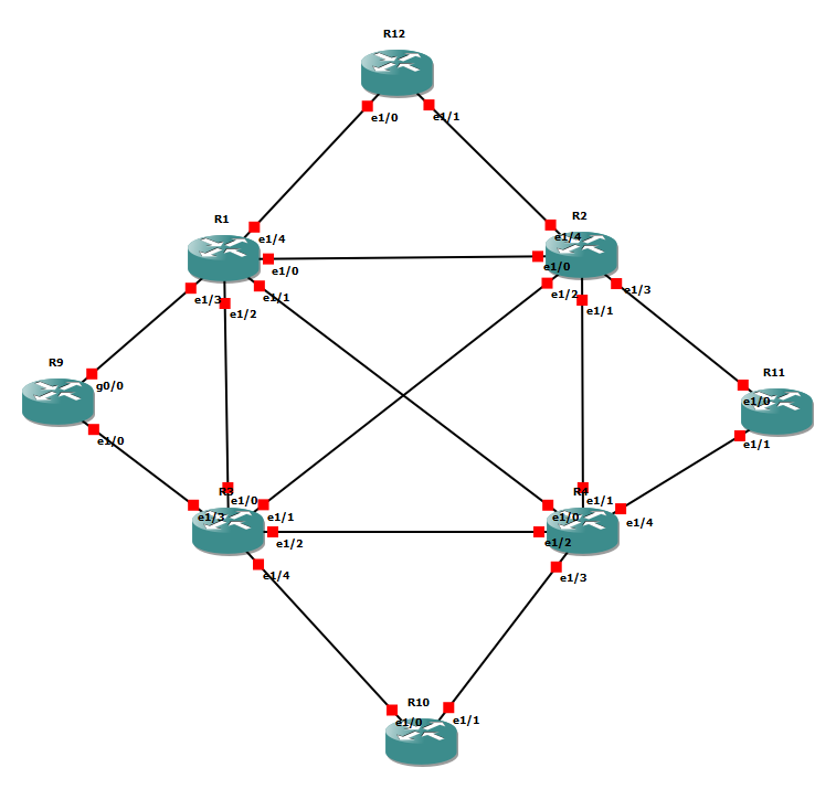
Core network example.
R1 through R4 are our core routers in this example. They’ll be making up the MPLS fabric. All of the other routers (R9 through R12) are our example distribution routers. They are connected with 2 L3 point-to-point links to two different cores. In the real world, this is many more routers connected to every possible pairing into the core mesh.
The usual way of doing this would be to have the distribution routers act as PE routers, terminating the L3 VPNs there. For now, we’ve got to do it at the core layer.
The original idea was to use OSPF to pass the distribution layer routes from the VRF instances back to the BGP core. While it works as a concept, there is a catch with it. Due to how administrative distances work, OSPF will always win against BGP. With our mesh of distribution routers split across the cores, this results in “better” routes along the distribution routers. Traffic would never properly traverse the core.
Simply adjusting the administrative distances so the MP-BGP routes win out wouldn’t help. The path to the distribution router would never be used. The traffic would simply loop round the core or be dropped.
The solution to this problem – route maps. In our case it’ll end up with some slightly odd looking results but solves our backdoor route solution.
We start by issuing every distribution router a tag number. In this small example, we’ve gone with the numbers of the routers. To apply this to the locally created routes, we add the following configuration:
router ospf 1
 redistribute connected subnets tag 9
The bit of cleverness in this configuration is that we don’t make the user facing interfaces OSPF interfaces. Instead we re-distribute them in and configure the router to add the tag. That does mean our point-to-point links won’t be picked up but they’ll be collected at the core end by redistributing connected subnets there.
On the core, our configuration is a bit more complicated:
router bgp 65101
 bgp log-neighbor-changes
 redistribute static
 neighbor 2.2.2.2 remote-as 65101
 neighbor 2.2.2.2 update-source Loopback1
 neighbor 3.3.3.3 remote-as 65101
 neighbor 3.3.3.3 update-source Loopback1
 neighbor 4.4.4.4 remote-as 65101
 neighbor 4.4.4.4 update-source Loopback1
 !
 address-family vpnv4
  neighbor 2.2.2.2 activate
  neighbor 2.2.2.2 send-community extended
  neighbor 3.3.3.3 activate
  neighbor 3.3.3.3 send-community extended
  neighbor 4.4.4.4 activate
  neighbor 4.4.4.4 send-community extended
 exit-address-family
 !
 address-family ipv4 vrf Demo
  redistribute connected
  redistribute ospf 2 route-map INBOUND
 exit-address-family
router ospf 2 vrf Demo
 redistribute bgp 65101 subnets
 distribute-list route-map INBOUND in
route-map INBOUND permit 10
 match tag 9 12
route-map INBOUND deny 20
Ok, that’s a lot to take in. So, let’s break it down a bit. Looking at the BGP configuration, we re-distribute the OSPF routes but only if they match our INBOUND route map. That route map looks for the tags specific to the distribution routers directly connected to said core.
The OSPF section is the most important part of this configuration. The critical bit is that while we will receive the full OSPF database but only allow routes from the “trusted” downstream routers to enter the routing table. This means that for anything not local, BGP wins out. We still maintain the ability to dynamically light up user subnets without creating the alternate path through the distribution routers.
Our routing table does look a bit odd though. Let’s look at an example distribution switch:
Codes: L - local, C - connected, S - static, R - RIP, M - mobile, B - BGP
       D - EIGRP, EX - EIGRP external, O - OSPF, IA - OSPF inter area
       N1 - OSPF NSSA external type 1, N2 - OSPF NSSA external type 2
       E1 - OSPF external type 1, E2 - OSPF external type 2
       i - IS-IS, su - IS-IS summary, L1 - IS-IS level-1, L2 - IS-IS level-2
       ia - IS-IS inter area, * - candidate default, U - per-user static route
       o - ODR, P - periodic downloaded static route, H - NHRP, l - LISP
       + - replicated route, % - next hop override
Gateway of last resort is 10.2.104.4 to network 0.0.0.0
S*    0.0.0.0/0 [1/0] via 10.2.104.4
                [1/0] via 10.2.103.3
      9.0.0.0/32 is subnetted, 1 subnets
O E2     9.9.9.9 [110/20] via 10.2.104.4, 00:16:53, Ethernet1/1
      10.0.0.0/8 is variably subnetted, 12 subnets, 2 masks
O IA     10.2.16.0/24 [110/11] via 10.2.104.4, 00:16:53, Ethernet1/1
                      [110/11] via 10.2.103.3, 00:16:54, Ethernet1/0
O        10.2.19.0/24 [110/21] via 10.2.103.3, 00:18:06, Ethernet1/0
O        10.2.39.0/24 [110/20] via 10.2.103.3, 00:18:06, Ethernet1/0
C        10.2.103.0/24 is directly connected, Ethernet1/0
L        10.2.103.10/32 is directly connected, Ethernet1/0
C        10.2.104.0/24 is directly connected, Ethernet1/1
L        10.2.104.10/32 is directly connected, Ethernet1/1
O        10.2.112.0/24 [110/31] via 10.2.103.3, 00:17:43, Ethernet1/0
O        10.2.114.0/24 [110/20] via 10.2.104.4, 00:17:43, Ethernet1/1
O        10.2.211.0/24 [110/30] via 10.2.104.4, 00:17:33, Ethernet1/1
O        10.2.212.0/24 [110/40] via 10.2.104.4, 00:17:33, Ethernet1/1
C        10.10.10.10/32 is directly connected, Loopback0
      11.0.0.0/32 is subnetted, 1 subnets
O E2     11.11.11.11 [110/20] via 10.2.103.3, 00:16:54, Ethernet1/0
      12.0.0.0/32 is subnetted, 1 subnets
O E2     12.12.12.12 [110/20] via 10.2.104.4, 00:16:53, Ethernet1/1
                     [110/20] via 10.2.103.3, 00:16:54, Ethernet1/0
Hang on, it’s still got all those round the houses paths in it! However, it is only connected to the core routers. Thus any traffic will hit the following routing table:
Routing Table: Demo
Codes: L - local, C - connected, S - static, R - RIP, M - mobile, B - BGP
       D - EIGRP, EX - EIGRP external, O - OSPF, IA - OSPF inter area
       N1 - OSPF NSSA external type 1, N2 - OSPF NSSA external type 2
       E1 - OSPF external type 1, E2 - OSPF external type 2
       i - IS-IS, su - IS-IS summary, L1 - IS-IS level-1, L2 - IS-IS level-2
       ia - IS-IS inter area, * - candidate default, U - per-user static route
       o - ODR, P - periodic downloaded static route, H - NHRP, l - LISP
       + - replicated route, % - next hop override
Gateway of last resort is not set
      9.0.0.0/32 is subnetted, 1 subnets
B        9.9.9.9 [200/20] via 1.1.1.1, 00:18:14
      10.0.0.0/8 is variably subnetted, 12 subnets, 2 masks
B        10.2.16.0/24 [200/0] via 1.1.1.1, 00:18:14
B        10.2.19.0/24 [200/0] via 1.1.1.1, 00:18:14
B        10.2.39.0/24 [200/0] via 3.3.3.3, 00:18:14
B        10.2.103.0/24 [200/0] via 3.3.3.3, 00:18:14
C        10.2.104.0/24 is directly connected, Ethernet1/3
L        10.2.104.4/32 is directly connected, Ethernet1/3
B        10.2.112.0/24 [200/0] via 1.1.1.1, 00:18:14
C        10.2.114.0/24 is directly connected, Ethernet1/4
L        10.2.114.4/32 is directly connected, Ethernet1/4
B        10.2.211.0/24 [200/0] via 2.2.2.2, 00:18:14
B        10.2.212.0/24 [200/0] via 2.2.2.2, 00:18:14
O E2     10.10.10.10/32 [110/20] via 10.2.104.10, 00:19:27, Ethernet1/3
      11.0.0.0/32 is subnetted, 1 subnets
O E2     11.11.11.11 [110/20] via 10.2.114.11, 00:19:04, Ethernet1/4
      12.0.0.0/32 is subnetted, 1 subnets
B        12.12.12.12 [200/20] via 1.1.1.1, 00:18:14
Look at all those lovely BGP routes through our MPLS core that take over. Just to make sure, let’s do a traceroute:
Type escape sequence to abort.
Tracing the route to 12.12.12.12
VRF info: (vrf in name/id, vrf out name/id)
  1 10.2.103.3 196 msec
    10.2.104.4 208 msec
    10.2.103.3 132 msec
  2 10.2.112.1 [MPLS: Label 23 Exp 0] 276 msec 404 msec 308 msec
  3 10.2.112.12 488 msec 352 msec 532 msec
Our traffic from R10 to R12 passes through R3/4, then R2 and onto 12. It gets labelled ahead long the inter-core link, which is exactly what we’re aiming for.
While this configuration is a little complicated, it’s the best of what we can do for now. It’s also been an eye opener in regards to the existing infastructure. We’ve learned it’s possible for traffic to route round campus while completely missing the inter-core links. Not a likely situation in any case but one to look though.
My next challenge is to take what I’ve got in GNS3 and translate it to Brocade. That should be the easy bit…