Virtualizing the Campus Network
I’ll be the first to admit that I never really intended to be talking about in-depth networking topics when I started this blog a few years back. However, that’s been where a lot of my focus and effort has gone in to recently. That said, I’m not completely broadcast free right now. I’m managing an STL antenna move and even tying an off the shelf alarm dialer into a silence detector for a volunteer group.
If that’s what you’re after, I’m afraid this post isn’t for you. If you’re interested in the world of virtual routing, MPLS and even a bit of BGP (why does everyone find it so scary?), this is the article for you. While I can’t claim to be an expert, they often say try teaching someone else to see if you can truly understand it yourself.
Probably the best way to kick this off is to look at what we’re aiming for. Physically, we’ll be building a small Core/Distribution/Access plus DC and external world configuration.
Logically, we’ll be building a number of virtual networks on top of this physical network.
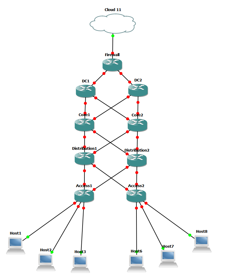
The physical topology we’ll be building.
Almost every link between routers on this diagram is layer 3 – IP routed. This creates an underlay network we can build on top of. Combine it with OSPF, and we’re off to a good start.
Except there’s a twist – we’ll be using MPLS rather than IP routing on the underlay. While there’s nothing stopping us from using IP routing for our underlay, MPLS is generally seen as less taxing on the routers/switches. Packets are labelled as they enter the MPLS network. It’s this label that’s used to quickly route packets. At each hop, the top label is removed and either replaced or popped off for the final hop as a standard IP packet.
In a little more detail, each route label switch router (that’s what they’re called in the MPLS world) goes through its routing table and assigns a label for each prefix. LDP is then used to pass this information between between the routers.
When it comes to actual operation, the incoming label (which is only locally significant) is looked up in the forwarding table. The router will then either change the label, thus carrying the packet further along the “circuit” or the label will be “popped” off. The latter is done at the penultimate hop, basically turning the packet back into an IP routed packet.
An example of this forwarding table in action can be found below:
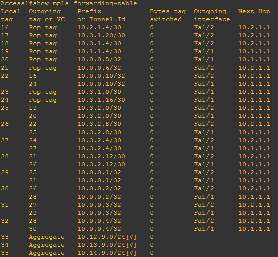
An MPLS forwarding table.
Here you can see that every subnet has a separate incoming and outgoing tag, which is unique to the router and subnet in question. Routes that are “close by” have the “pop tag” action outbound. This is the penultimate hop issue I mentioned earlier.
Most of the other subnets have tag numbers that get attached. These are used whether the traffic originates here or not. The incoming tag is compared against this table in order to determine the next action. As you can see, this is much simpler and quicker than normal IP route calculations.
Back to the wider picture and some other key reasons for of MPLS over IP routing include the support for L2 and L3 VPNs (we’ll be demonstrating the latter) and hiding network complexity (the edge doesn’t need to know what the underlay network looks like).
The labels used are for each route are agreed between routers using the LDP protocol in our example. While we could configure it on a per-router/interface basis, we’ll actually be telling the router to enable LDP on every interface that OSPF knows about. It simplifies the configuration and gives us one less issue to worry about.
Just before we get into the real meat and potatoes of configuring the network, there’s a little more background we need to know. With MPLS, you’re effectively acting as your own ISP. In the core, you’ll be making use of provider routers. These forward traffic using MPLS and for our small example network, they’ll also act as BGP route reflectors (simplifying the BGP configuration).
Hang on a moment, what’s this about BGP? That’s to do with the PE (provider edge) routers you’ll also be running. These are use to pass customer routes between VPN “endpoints”. For a campus network, each network (e.g. Staff, Student, Faculty) is a separate customer. We don’t want them interacting with each other.
To prevent the routes leaking into each other we make use of two key technologies. The first of these is something called Virtual Routing and Forwarding (VRF) in the Cisco world or VPN Instance in the HPE Comware world. This allows us to have a separate routing table for each “customer” at the PE router.
If we simply distributed these routes into BGP or OSPF as-is, we’d lose the segregation we’re after. That’s where MP-BGP VPNv4 feature and an MPLS feature come in. On the MPLS side, we give each VPN (that’s what each “customer’s” network really is) a route distinguisher. This is of the form [AS NUMBER]:[VPN ID] and gets attached to the front of the IPv4 route (we’re doing IPv4 only here to keep things simple). This makes sure each IPv4 route that any customer has is truely unique – traffic can’t leak between them.
The Multi-Protocol BGP VPNv4 feature comes in as a extension to the BGP routing protocol. That’s what we’ll be using to distribute the customer routes around the “ISP” core.
However, you still need to map from the customer’s virtual routing table to the MPLS VPN. That’s what the route target on the VRF does. It’s of the same format as the route distinguisher and in our case will be identical.
Finally, it’s worth noting that in this design, we will be placing the L3 boundary at the access layer. In most MPLS L3 VPN arrangements, the PE and Customer Edge (CE) routers have to talk a common routing protocol (e.g. BGP). This then passes the customer routes in and out. We’d need to do that for every VRF the access layer will be presenting.
As we’re only needing to provide some flat subnets on the edge, it’s much simpler to present these directly on the access router/switch. We can then redistribute the the connected routes in the VRFs into MP-BGP VPNv4. Much simpler than running multiple routing protocol instances between a potential PE and CE.
That’s a lot to take in but we’re now ready to configure those routers! It’s not quite got the same oomph as “move that bus” but hey-ho, let’s crack on.
The configuration for our core routers looks something like this:
hostname Core1

ipv6 unicast-routing

!

interface Loopback0

ip address 10.0.0.1 255.255.255.255

ip ospf 1 area 0

ipv6 address FD00:0:0:1::/64 eui-64

ipv6 ospf 1 area 0

!

interface FastEthernet1/1

no switchport

ip address 10.3.2.2 255.255.255.252

ip ospf 1 area 0

ipv6 address FD00:3:2:1::/64 eui-64

ipv6 ospf 1 area 0

!

interface FastEthernet1/2

no switchport

ip address 10.3.2.10 255.255.255.252

ip ospf 1 area 0

ipv6 address FD00:3:2:9::/64 eui-64

ipv6 ospf 1 area 0

!

interface FastEthernet2/1

no switchport

ip address 10.3.1.1 255.255.255.252

ip ospf 1 area 0

ipv6 address FD00:3:1:1::/64 eui-64

ipv6 ospf 1 area 0

!

interface FastEthernet2/2

no switchport

ip address 10.3.1.5 255.255.255.252

ip ospf 1 area 0

ipv6 address FD00:3:1:5::/64 eui-64

ipv6 ospf 1 area 0

!

router ospf 1

mpls ldp autoconfig

log-adjacency-changes

!

router bgp 65000

no synchronization

bgp log-neighbor-changes

neighbor 10.0.0.2 remote-as 65000

neighbor 10.0.0.2 update-source Loopback0

neighbor 10.0.0.2 route-reflector-client

neighbor 10.0.0.3 remote-as 65000

neighbor 10.0.0.3 update-source Loopback0

neighbor 10.0.0.3 route-reflector-client

neighbor 10.0.0.4 remote-as 65000

neighbor 10.0.0.4 update-source Loopback0

neighbor 10.0.0.4 route-reflector-client

neighbor 10.0.0.5 remote-as 65000

neighbor 10.0.0.5 update-source Loopback0

neighbor 10.0.0.5 route-reflector-client

neighbor 10.0.0.6 remote-as 65000

neighbor 10.0.0.6 update-source Loopback0

neighbor 10.0.0.6 route-reflector-client

neighbor 10.0.0.7 remote-as 65000

neighbor 10.0.0.7 update-source Loopback0

neighbor 10.0.0.7 route-reflector-client

neighbor 10.0.0.8 remote-as 65000

neighbor 10.0.0.8 update-source Loopback0

neighbor 10.0.0.8 route-reflector-client

neighbor 10.0.0.9 remote-as 65000

neighbor 10.0.0.9 route-reflector-client

neighbor 10.0.0.10 remote-as 65000

neighbor 10.0.0.10 update-source Loopback0

no auto-summary

!

address-family vpnv4

neighbor 10.0.0.2 activate

neighbor 10.0.0.2 send-community both

neighbor 10.0.0.2 route-reflector-client

neighbor 10.0.0.3 activate

neighbor 10.0.0.3 send-community both

neighbor 10.0.0.3 route-reflector-client

neighbor 10.0.0.4 activate

neighbor 10.0.0.4 send-community both

neighbor 10.0.0.4 route-reflector-client

neighbor 10.0.0.5 activate

neighbor 10.0.0.5 send-community both

neighbor 10.0.0.5 route-reflector-client

neighbor 10.0.0.6 activate

neighbor 10.0.0.6 send-community both

neighbor 10.0.0.6 route-reflector-client

neighbor 10.0.0.7 activate

neighbor 10.0.0.7 send-community both

neighbor 10.0.0.7 route-reflector-client

neighbor 10.0.0.8 activate

neighbor 10.0.0.8 send-community both

neighbor 10.0.0.8 route-reflector-client

neighbor 10.0.0.9 activate

neighbor 10.0.0.9 send-community both

neighbor 10.0.0.9 route-reflector-client

neighbor 10.0.0.10 activate

neighbor 10.0.0.10 send-community both

neighbor 10.0.0.10 route-reflector-client

exit-address-family

!
Ok, it’s not quite the whole configuration but it’s the important bits. In this example, the fastEthernet 1/x interfaces point north, the 2/x interfaces point south.
Looking at a couple of the interfaces, you can see I’ve given them IPv4 and IPv6 addresses:
interface Loopback0

ip address 10.0.0.1 255.255.255.255

ip ospf 1 area 0

ipv6 address FD00:0:0:1::/64 eui-64

ipv6 ospf 1 area 0

!

interface FastEthernet1/1

no switchport

ip address 10.3.2.2 255.255.255.252

ip ospf 1 area 0

ipv6 address FD00:3:2:1::/64 eui-64

ipv6 ospf 1 area 0
While the latter isn’t strictly needed in our case, I’ve given every point-to-point link at /30. I’ve also created a /32 loopback that will act as the router ID in OSPF and also the peer address in BGP.
In both cases, you should really use some form of authentication and look into restricting access to the services remotely. In the lab, we can get away without any authentication.
Another point worth noting in the configuration of these interfaces is the specific OSPF configuration on each interface. It’s an approach I’ve always taken and ensures OSPF is only enabled where I want it.
Talking of OSPF:
router ospf 1

mpls ldp autoconfig

log-adjacency-changes
You can see that we’ve told it to enable MPLS and LDP on every interface the OSPF process is configured on. The configuration here is a little lazy (we don’t really care about what label ranges are used) but it works.
While the OSPF configuration is simple, the BGP configuration is a little more involved:
router bgp 65000

no synchronization

bgp log-neighbor-changes

neighbor 10.0.0.2 remote-as 65000

neighbor 10.0.0.2 update-source Loopback0

neighbor 10.0.0.2 route-reflector-client

address-family vpnv4

neighbor 10.0.0.2 activate

neighbor 10.0.0.2 send-community both

neighbor 10.0.0.2 route-reflector-client
The first section sets up the neighbors this router will be speaking with. The neighbors are in the same private AS as this router and will be connected to through the loopback interface. Note that this means OSPF (and MPLS) has to be up before BGP will setup the neighborship.
Another point of note is the “route-reflector-client” setting. This is only seen on the core routers and and is part of the BGP route reflector configuration. Rather than setting up a full mesh between all of the BGP speaking routers, we setup the core routers to act as route reflectors and pass updates between the other routers.
The next key part in the BGP configuration is the VPNv4 section. This is the extension/feature we will be using to pass customer routes between PE routers. We have to specifically activate the feature for each peer, enabling the sending of appropriate communities as part of Multi-Protocol BGP and act as a route reflector. The last part only appears on core routers.
With the core configured, we can look to the distribution layer. This is similar in configuration to the core but only talks to the core routers as peers and doesn’t have any specific route reflector settings. It’s not too exciting so let’s move onto the access layer.
ip vrf Faculty

rd 65000:120

route-target export 65000:120

route-target import 65000:120

!

ip vrf Staff

rd 65000:130

route-target export 65000:130

route-target import 65000:130

!

ip vrf Student

rd 65000:140

route-target export 65000:140

route-target import 65000:140

!

interface Loopback0

ip address 10.0.0.9 255.255.255.255

ip ospf 1 area 0

ipv6 address FD00:0:0:9::/64 eui-64

ipv6 ospf 1 area 0

!

interface FastEthernet1/1

no switchport

ip address 10.1.1.2 255.255.255.252

ip ospf 1 area 0

ipv6 address FD00:1:1:1::/64 eui-64

ipv6 ospf 1 area 0

!

interface FastEthernet1/2

no switchport

ip address 10.2.1.2 255.255.255.252

ip ospf 1 area 0

ipv6 address FD00:2:1:1::/64 eui-64

!

interface FastEthernet2/1

switchport access vlan 120

!

interface FastEthernet2/2

switchport access vlan 130

!

interface FastEthernet2/3

switchport access vlan 140

!

interface Vlan120

description Faculty

ip vrf forwarding Faculty

ip address 10.12.9.254 255.255.255.0

ipv6 address FD00:12:0:9::/64 eui-64

!

interface Vlan130

ip vrf forwarding Staff

ip address 10.13.9.254 255.255.255.0

ipv6 address FD00:13:0:9::/64 eui-64

!

interface Vlan140

ip vrf forwarding Student

ip address 10.14.9.254 255.255.255.0

ipv6 address FD00:14:0:9::/64 eui-64

!

router ospf 1

mpls ldp autoconfig

log-adjacency-changes

!

router bgp 65000

no synchronization

bgp log-neighbor-changes

neighbor 10.0.0.1 remote-as 65000

neighbor 10.0.0.1 update-source Loopback0

neighbor 10.0.0.2 remote-as 65000

neighbor 10.0.0.2 update-source Loopback0

no auto-summary

!

address-family vpnv4

neighbor 10.0.0.1 activate

neighbor 10.0.0.1 send-community both

neighbor 10.0.0.2 activate

neighbor 10.0.0.2 send-community both

exit-address-family

!

address-family ipv4 vrf Student

redistribute connected

no synchronization

exit-address-family

!

address-family ipv4 vrf Staff

redistribute connected

no synchronization

exit-address-family

!

address-family ipv4 vrf Faculty

redistribute connected

no synchronization

exit-address-family

!
Again, it’s a lot to take in but let’s break it down. First, we configure our VRFs:
ip vrf Faculty

rd 65000:120

route-target export 65000:120

route-target import 65000:120
Remember that route designator and route target we were talking about. This is where we map it onto a specific, local VRF on the access router.
As this is an access router/switch, we need to map the local VLAN IP interface onto the VRF:
interface Vlan120

description Faculty

ip vrf forwarding Faculty

ip address 10.12.9.254 255.255.255.0

ipv6 address FD00:12:0:9::/64 eui-64
So, at this point we’ve now got the local IP interface and VLAN mapped. Remember to create the VLAN in the local database and configure some user facing ports (that’s what the fastEthernet 2/x ports are for).
Our final step is to get the routes into the MP-BGP VPNv4 feature:
address-family ipv4 vrf Faculty

redistribute connected

no synchronization

exit-address-family
As I mentioned before, we’re not peering with an external consumer. Instead, we’ll be advertising connected routes on what is technically our PE router.
We can check the whole lot is running in a couple of ways. Firstly, let’s look at the show ip route vrf Student command on an access router.
We can also see the complete set of VPNv4 routes for all customers using the show bgp vpnv4 unicast all command.
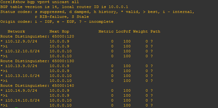
It’s worth noting that we don’t currently have a default route yet. However, we can see every customer route, along with the unique distinguisher.
So, lets get that default route to be the firewall. In the real world, we’d have the firewall, DC1 and DC2 all connected on VLANs. For this exercise, they’ll remain L3 routed interfaces. Mainly because switching simulation on GNS3 can still be a bit hit or miss.
Our firewall configuration looks something like this:
interface FastEthernet0/0

no ip address

duplex auto

speed auto

!

interface FastEthernet0/0.120

encapsulation dot1Q 120

ip address 10.12.0.1 255.255.255.252

ip ospf 120 area 0

!

interface FastEthernet0/0.130

encapsulation dot1Q 130

ip address 10.13.0.1 255.255.255.252

ip ospf 130 area 0

!

interface FastEthernet0/0.140

encapsulation dot1Q 140

ip address 10.14.0.1 255.255.255.252

ip ospf 140 area 0

!

interface FastEthernet0/1

no ip address

duplex auto

speed auto

!

interface FastEthernet0/1.120

encapsulation dot1Q 120

ip address 10.12.0.5 255.255.255.252

ip ospf 120 area 0

!

interface FastEthernet0/1.130

encapsulation dot1Q 130

ip address 10.13.0.5 255.255.255.252

ip ospf 130 area 0

!

interface FastEthernet0/1.140

encapsulation dot1Q 140

ip address 10.14.0.5 255.255.255.252

ip ospf 140 area 0

!

router ospf 120

log-adjacency-changes

default-information originate

!

router ospf 130

log-adjacency-changes

default-information originate

!

router ospf 140

log-adjacency-changes

default-information originate

!

ip route 0.0.0.0 0.0.0.0 192.168.1.254
In reality we wouldn’t have a router acting as a dumb “firewall” allowing all of our virtual networks to freely talk to each other. However, there are a couple of points to note.
Firstly, we have three separate OSPF instances. Doing this allows us to have fully segregated routing tables on the MPLS infrastructure. Technically, we could get away with one instance but routes would leak and allow users to bounce traffic between roles without hitting the firewall.
Secondly, we have a default route that we advertise out of the OSPF instances. This is what will be redistributed into MP-BGP VPNv4. Talking of which, the redistribution will happen in the DC routers.
ip vrf Faculty

rd 65000:120

route-target export 65000:120

route-target import 65000:120

!

ip vrf Staff

rd 65000:130

route-target export 65000:130

route-target import 65000:130

!

ip vrf Student

rd 65000:140

route-target export 65000:140

route-target import 65000:140

!

interface Loopback0

ip address 10.0.0.3 255.255.255.255

ip ospf 1 area 0

ipv6 address FD00:0:0:3::/64 eui-64

ipv6 ospf 1 area 0

!

interface FastEthernet0/0

no ip address

duplex auto

speed auto

!

interface FastEthernet0/0.120

encapsulation dot1Q 120

ip vrf forwarding Faculty

ip address 10.12.0.2 255.255.255.252

ip ospf 120 area 0

!

interface FastEthernet0/0.130

encapsulation dot1Q 130

ip vrf forwarding Staff

ip address 10.13.0.2 255.255.255.252

ip ospf 130 area 0

!

interface FastEthernet0/0.140

encapsulation dot1Q 140

ip vrf forwarding Student

ip address 10.14.0.2 255.255.255.252

ip ospf 140 area 0

!

interface FastEthernet0/1

no ip address

shutdown

duplex auto

speed auto

!

interface FastEthernet2/1

no switchport

ip address 10.3.2.1 255.255.255.252

ip ospf 1 area 0

ipv6 address FD00:3:2:1::/64 eui-64

ipv6 ospf 1 area 0

!

interface FastEthernet2/2

no switchport

ip address 10.3.2.5 255.255.255.252

ip ospf 1 area 0

ipv6 address FD00:3:2:5::/64 eui-64

ipv6 ospf 1 area 0

!

router ospf 120 vrf Faculty

log-adjacency-changes

redistribute bgp 65000 subnets

!

router ospf 130 vrf Staff

log-adjacency-changes

redistribute bgp 65000 subnets

!

router ospf 140 vrf Student

log-adjacency-changes

redistribute bgp 65000 subnets

!

router ospf 1

mpls ldp autoconfig

log-adjacency-changes

!

router bgp 65000

no synchronization

bgp log-neighbor-changes

neighbor 10.0.0.1 remote-as 65000

neighbor 10.0.0.1 update-source Loopback0

neighbor 10.0.0.2 remote-as 65000

neighbor 10.0.0.2 update-source Loopback0

no auto-summary

!

address-family vpnv4

neighbor 10.0.0.1 activate

neighbor 10.0.0.1 send-community both

neighbor 10.0.0.1 route-reflector-client

neighbor 10.0.0.2 activate

neighbor 10.0.0.2 send-community both

neighbor 10.0.0.2 route-reflector-client

exit-address-family

!

address-family ipv4 vrf Student

redistribute connected

redistribute ospf 140 vrf Student match internal external 1 external 2

default-information originate

no synchronization

exit-address-family

!

address-family ipv4 vrf Staff

redistribute connected

redistribute ospf 130 vrf Staff match internal external 2

default-information originate

no synchronization

exit-address-family

!

address-family ipv4 vrf Faculty

redistribute connected

redistribute ospf 120 vrf Faculty match internal external 2

default-information originate

no synchronization

exit-address-family

!
As you can see, our VRFs remain as before. However, there is a slight change to the interface configuration:
interface FastEthernet0/0.120

encapsulation dot1Q 120

ip vrf forwarding Faculty

ip address 10.12.0.2 255.255.255.252

ip ospf 120 area 0
Specifically, each interface for each role is in a different OSPF instance. Talking of which, we actually have a further OSPF instance on this router. It’s instance 1 and is part of the MPLS underlay we’ve been running throughout.
Now, at this point, we have several OSPF instances with a default route and ready to go. However, we need to redistribute this into BGP in order to get it down to the access layer networks. To do this, we add a few lines to the BGP configuration on the DC routers:
address-family ipv4 vrf Student

redistribute connected

redistribute ospf 140 vrf Student match internal external 1 external 2

default-information originate

no synchronization

exit-address-family
Note that you need to match up the OSPF instance with the correct VRF. Not to worry if you muck it up though, IOS will tell you.
One thing we do need to do is make sure we match both internal and external routes. This is because our default route (0.0.0.0/0) is an OSPF E2 route. We also need to tell BGP we really do want to advertise the default route as well. Otherwise, we’d get everything else but.
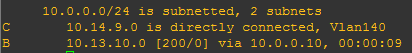
At this point we now have a default route from the access layer. That’s neat and we can check it works by looking at the routing table on a VRF:
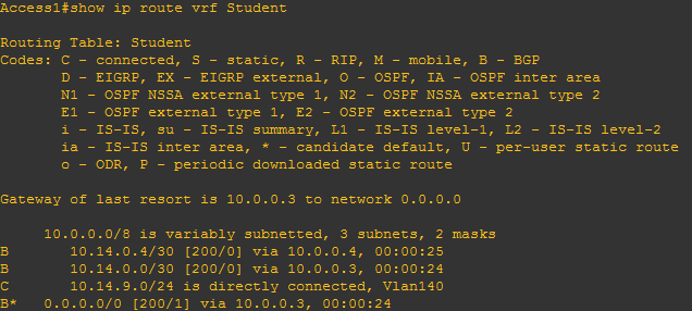
The routing table for the Student VRF on an access router.
We’ve now got the default route as mentioned above as well as the routes in DC and the existing MPLS VPN routes. It’s a nice, compact looking routing table.
However, we’ve not quite finished. We also need to advertise the routes from BGP into OSPF. We do this by specifically ensuring that subnets (not just classful routes) as redistributed:
router ospf 130 vrf Staff

log-adjacency-changes

redistribute bgp 65000 subnets
The result is a rather more populated routing table on the firewall. Note that because we don’t give the firewall access to the MPLS underlay, only the overlay networks are seen.
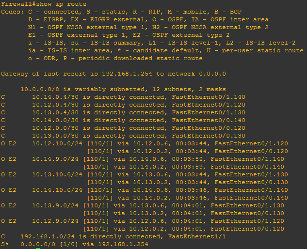
The routing table on the firewall.
With everything up and running, let’s test it by pinging then tracing the route between different roles on the two access routers:
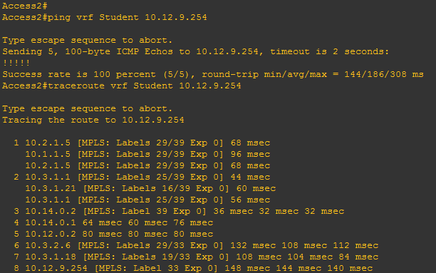
A ping and traceroute between roles on different access routers.
We can see the firewall is doing its job in this lab in that we’re now able to ping across roles. The traceroute confirms that we’re definitely not leaking anywhere on the MPLS network and do indeed bounce through the firewall.
While this is a bit more complicated than a traditional campus network, you’ll hopefully now see that it’s not too difficult to get going. The security benefits and flexibility through using MPLS should be apparent. This is despite the fact we didn’t even touch things like L2 VPNs (hint, look at the xconnect command in the Cisco world).
If you’ve got access to the equipment, I’d recommend giving it a go yourself. You never know, you might even learn something.