Pretty LEDs
Looks at photos modern radio studios in the UK and you’ll see two things. Firstly, there’s all those TV screens hung on walls to deliver dynamic branding. They may look the part but the audio engineer in me can’t help but consider the reflection problems it’ll bring in over proper soundproofing.
On a cheerier note, you’ll also see a lot of LEDs under desks now. Done badly, it’s something that makes it look like you took your studio design inspiration from Need for Speed. Done properly, it can be quite tasteful. Especially if you’re changing the colour to match function (i.e. red for MIC LIVE) rather than just slamming it in disco mode.
That said, there is nothing stopping you from modifying the Christmas Sound to Light circuit I told you about…
Either way, it’s been on my radar recently. There’s a volunteer radio station I’m doing work with that could really do with a complete studio refurb. As part of it, they’re wanting to go down the LED route.
It’s at this point one of my colleagues came back with a £400 quote for tri-colour LED strips and associated controller mechanism. The plan was to use a Raspberry Pi and MDX controller to do the magic.
Now I’m all game for engineering things properly. In fact, I’m always taking the time to automate tasks over doing them manually. I’m sick of snowflakes and hand-cranked donkey work in IT.
But in this case – we needed some simplicity. After all, we only wanted to change the colour when a microphone was live or telephone call was incoming. With that in mind, I cracked out the finest CAD tools (somewhat inspired by this chap):
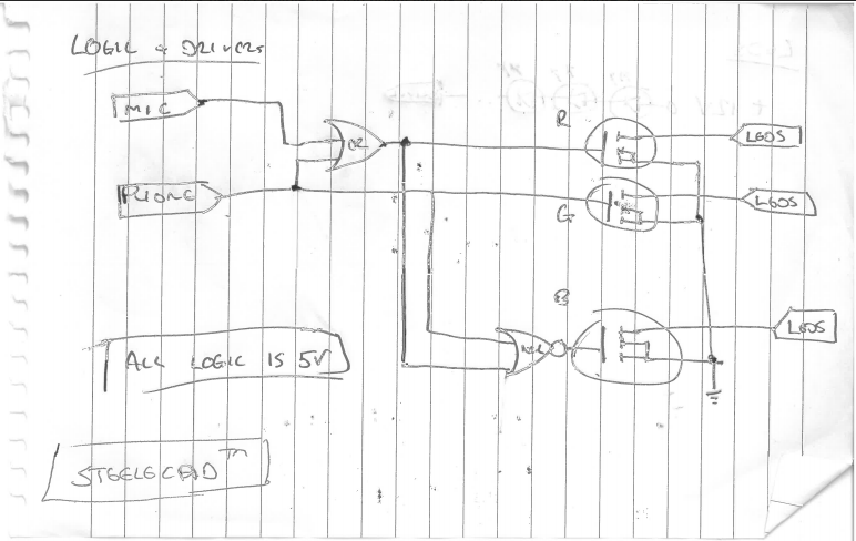
The main circuit diagram.
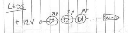
The LED strip part of the circuit diagram.
It’s about as simple as you can make it and comes in at well under £100. However, it’s not the first time I’ve looked to electronics to simplify a job.
A little while back, I needed build a remote monitoring unit – a bit of kit that allows you to dial in and listen to an audio stream. My original design for it was based round a micro-controller or PIC. Well, that’s until a colleague challenged me to design it from TTL logic only.
Surprisingly, you can do it and I’ve still got the circuit diagram. It’s got some clever features like using a decade counter for ring count and pickup. Oh, and the classic 555 timer for call time-out, which in turn simply hits reset on the counter to end the call.
Thankfully for BT’s sake, it never did get built but you’ll find the schematic here if you’re brave enough to give it a shot.