Sound to Light Christmas
Pop into most radio stations and you’ll soon see Christmas decorations going up in the offices and studios. In most cases, it’ll be some lights, tinsel and maybe even the odd electronic reindeer in October (don’t ask!).
Where the local engineer has been a bit more inventive, you might even see a tree with lights hooked into the MIC live circuit. In one case, I’ve even seen a fully motorised tree which blows snow when the microphones are off (it was a bit noisy).
A few years back I got the idea to make sound to light Christmas lights. The idea being that the lights flashed in time with the sound of the station.
While it’s the sort of cheesy thing you might see from a disco DJ, it seemed a nice addition to the studios.
The slightly alarming bit is that it took me a couple of attempts to get right. It turns out that a relay switching on and off at a rate of knots acts as a crude spark gap generator. Put it near a mixer with MIC lines going into and you end up with an unfortunate buzzing sound on the radio.
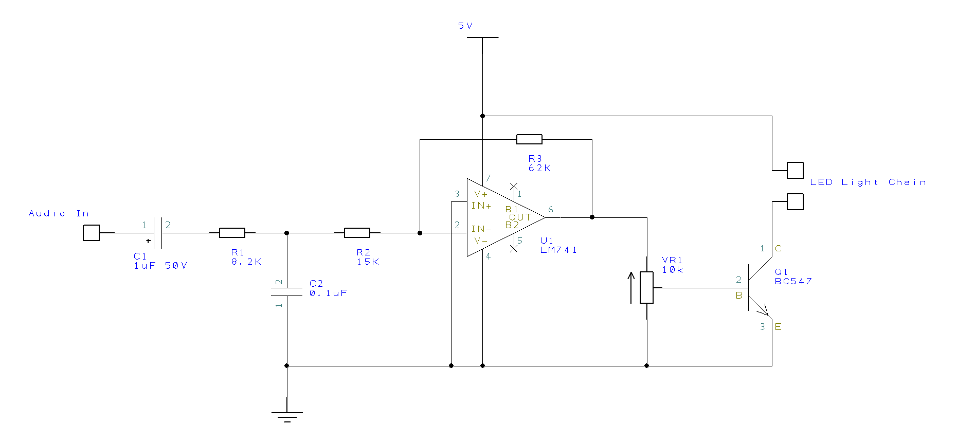
For that reason, the circuit I’ve built and are sharing with you now is all solid state. I can also say it’s been used in the studios several times now and looks something like this (click the image to download in a higher resolution):
Best bit is that it’s not too complicated and something you should be able to build with spares kicking around any radio station. Even if your soldering skills are as shockingly lacking as mine.
Anyway, you’ll need:
- 1x op-amp (LM74x or similar).
- 1x NPN Transistor (BC547 or similar).
- 1x 1uF electrolytic capacitor.
- 1x 0.1uF ceramic capacitor.
- 1x 15K resistor.
- 1x 8k2 resistor.
- 1x 62K resistor.
- 1x 10K pot.
- 1x low voltage Christmas light chain (one driven by batteries is a good shout – pound shops aren’t a bad place to source these).
You may be able to change some of the values for your own build. I mainly used whatever was available to me at the time.
Either way, the circuit’s operation isn’t particularly complicated. It starts with a single in-line capacitor. This is used as a way to remove DC bias from the signal. We’re only interested in the audio waveform.
While we’re on the topic of audio input, you’ll want it unbalanced, at line level and with the ground connected to this circuit’s ground.
Next step in the circuit is a crude RC low-pass filter. The values I used (8k2 and 0.1uF) result in around 200Hz as the cut-off frequency. That’s not a bad place to choose for only getting the “beats” of the music.
The next step in the circuit is the op-amp. We use this in an inverting configuration to amplify the signal. The idea is to get the voltage high enough to trigger the transistor later in the circuit.
We also do something a little nasty here. You’ll see the negative rail of the op-amp is hooked into ground. The idea is that we flatten the bottom half of any wave. We’re only interested in the positive peaks.
On the up side, the op-amp helps provide a bit of isolation between the two parts of the circuit.
Once we’ve got this positive voltage only signal, we put it through a 10K potentiometer wired as a potential divider. This allows tweaking of the “trigger level”. It’s this control that you’ll adjust on installation to set the behaviour of the lights.
Finally, the signal from the potentiometer is delivered to a transistor. This is what triggers the lights on and off.
For safety’s sake, I’ve used a low voltage (but short) LED light chain here. If you want to replace this to feed something else, you can do. However, I’m holding no responsibility for anything you fry or kill. The flashing in time of your mixer followed by the release of magic smoke as you back feed 240V into it never goes down well.
On a more positive note, this isn’t a complicated circuit and I’m sure you can probably improve vastly upon it. Either way, it’ll make a nice festive addition for the studio.