Making the Hop
It’s something I’ve briefly mentioned in the past but not something I’ve ever covered in detail. However, it is something that’s appeared on my radar again – point-to-point WiFi links.
While I’ve never been expert in RF, I will talk you through using the Radio Mobile tool to give you a good idea if a link in feasible without having to trek out the office. Of course, there are some things you can’t determine without making a site visit (e.g. foliage in the way, large buildings along the route) but it’s a reasonable estimate.
To begin, make sure you’ve installed Radio Mobile and configured both Google Maps and STRM data. We’ll be using those for terrain and mapping information. There’s a few different guides for doing this but following the installation guide on the author’s website is a good start.
The main focus of this article is being able to work out if a planned radio link is at least feasible. To work this out, and before we do any actual modelling, we need two pieces of information. The first of these is regulatory.
There will most likely be restrictions on both the power and bands you can use in your location. Well, unless you’re setting this up in the middle of the ocean or somewhere appropriately sunny like Antartica.
Here in the UK, the maximum power you can use for such a link is 4W EIRP. That means 4W as theoretically measured out of the antenna, not generated by the radio. It also assumes you’ll be using the licensed Band C spectrum which does have a cost per endpoint. If you’re wanting to avoid that, you’ll be even more limited to 1W EIRP in the rest of the 5GHz space.
That’s not the only concern you’ll have when planning for such a link. You also need to know the technical specifications of the equipment you’re planning on using. Specifically, you’ll need to know gain of your antennas (measured in dBi [dB in respect to an isotropic antenna] or dBd [dB in respect to a dipole antenna]).
From that we can roughly calculate the forward power needed. A good way to do this is use to convert the 4W EIRP figure into a dBW (dB in respect to a watt) figure. Using this tool, we get about 6dbW.
For the next bit you’ll need you technical specifications in front of you. If you want a reasonable example to follow through with, take a look at the datasheet for Ubiquti’s 5GHz airFiber range. In this example, you’ll see an antenna gain of 23 dBi.
Removing this from our dBW value earlier give a value of roughly -17dBW. Or, if we punch that back into the converter 0.02W forward power. Sounds small but will get you near the maximum 4W EIRP as allowed by the regulator.
Armed with that information, you can now configure the radio link in Radio Mobile. To do this select File –> Network Properties from the menu. On the first screen, set the frequency range for the spectrum you’re planning on using.
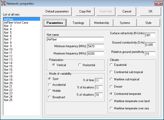
Setting the overall network properties.
You’ll need to give the network a sensible name. You’ll also need to enter the frequency range you’ll be operating in. In our example, I’ve been looking at 5GHz Band C.
Now select the system tab. There are a number of settings you’ll want to adjust.
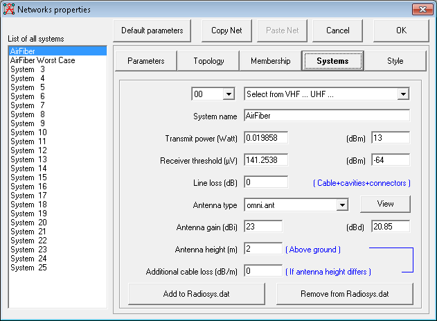
The airFiber Network Settings
The first of these is the system name. Call it something sensible. In our example, I actually ended up configuring two different networks to represent a couple of possible data rates for the equipment being considered.
The transmit power in watts or dBm should be entered as we calculated earlier. The reciever threshold data you will get from the spec sheet. It’s worth noting that you’ll see a number of different sensitivities listed. These relate to the different modulations used for transmission. The short version is that the slower the data rate, the more likely it is to be picked up. Enter the receiver sensitivity for the data rate you’re aiming to achieve. Note that we’ll be modelling the best case.
The final details that need to be entered relate to the antenna. Weirdly, the antenna pattern isn’t so important to what we’re looking to achieve here. If you were planning for a broadcast or looking at potential coverage, it’s required. Here, we just need to make sure that properly aligned antennas will likely work.
What is important though is the gain level of the antenna. Enter is in either the dBi or dBd box. We won’t be modelling feeder cable loss.
With that in place, you can now configure the endpoints in your network. For this step, you will need to know the height of the antenna above ground level. If you’re not sure about this, a good rough guide is approximately 2m for every story you go up.
Either way, select the Membership tab and enter the antenna heights.
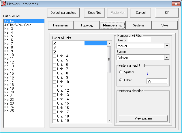
Antenna height details being entered.
With that configured, click on OK to save the changes. While you know the heights of the endpoints, you won’t know the names or locations yet. To configure this, select File –> Unit Properties
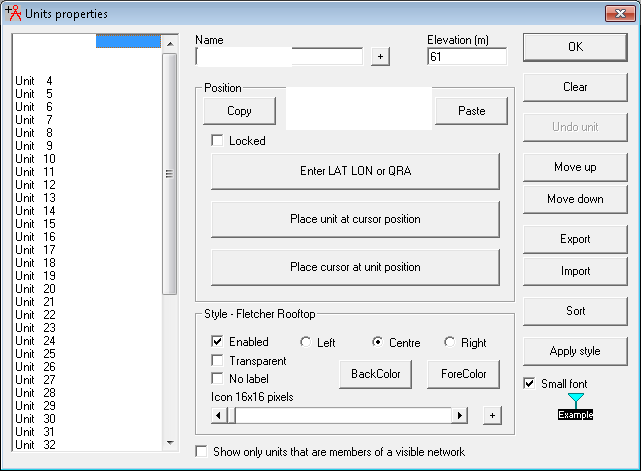
Configuring the unit properties.
You will need to enter the latitude and longitude of each endpoint. It’s also worth giving it a sensible name as well.
And with that, we’re now ready to try some link. To do this, select Tools –> Radio Link from the menu. As an example, here’s the output from a long distance option I was looking at:
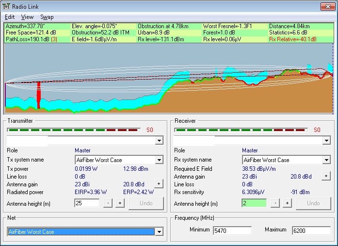
Prediction for the long distance link.
As you can see, I’ve selected a couple of endpoints from the drop-down menus on the TX and RX sides. I’ve also selected the lower speed (but more robust) option from the drop-down menu at the bottom of the screen.
The important bits to note here are the TX/RX signal levels and the elliptical shape drawn in the plot at the top. The signal levels are self explanatory. However, the elliptical shape is the important bit. This represents the predicted Fresnel Zone. Any object in this area will likely cause interference through reflection or blocking.
In our example, it’s even worse – there’s solid ground in the way. There’s no way this radio link is ever going to work.
On a cheerier note, here’s an example of a radio link that should work:
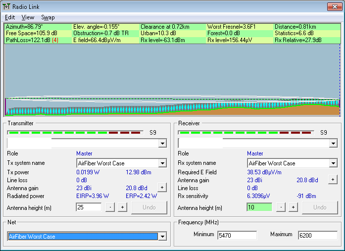
Shorter airFiber hop.
As you can see, the signal is solid and there’s no likely interference from terrain. That said, the blue “urban” shading is crossed, suggesting that there may be issues with getting a completely clear route.
While we may now have evidence the plot should work, your job is not quite yet finished. Site surveys will need to be done. After all, it’s not until you get on-site that you’ll see the tall buildings or trees that might cause you trouble.